The Building Blocks of Digital Logic: Meet the Gates!
Welcome back to our journey into the digital world! In our last post, we saw how computers use a simple language of 0s and 1s (binary) to represent everything. But how do they actually do anything with those 0s and 1s? How do they make decisions?
The answer lies in simple electronic circuits called logic gates. These are the fundamental building blocks of all digital systems, from the simplest calculator to the most powerful supercomputer. In this post, we will explore the three most basic logic gates that form the basis for building more complex logic gates.
What Are We Working With? Boolean Logic.
Before we meet the gates, we need to understand the rules of the game. Digital logic is based on a system developed by George Boole in the 1850s, called Boolean algebra. It’s much simpler than regular algebra because variables can have only one of two values: True (1) or False (0).
In digital circuits, these values are represented by voltage levels: a HIGH voltage is a 1 (True), and a LOW voltage is a 0 (False). Logic gates are the circuits that take these HIGH/LOW inputs and produce a specific HIGH/LOW output based on a rule. We can describe these rules using a simple chart called a truth table, which lists every possible input combination and the resulting output.
1. The OR Gate: The “Either/Or” Decision
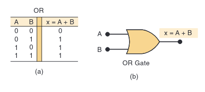
The first basic gate is the OR gate. An OR gate’s output will be HIGH (1) if any of its inputs are HIGH (1). The only way to get a LOW (0) output is if all inputs are LOW (0).
Analogy: The Party Invitation. Imagine you’ll go to a party if your friend Alex goes OR your friend Blair goes.
- If neither Alex nor Blair goes (Input A=0, Input B=0), then you don’t go (Output=0).
- If Alex goes but Blair doesn’t (Input A=1, Input B=0), then you go (Output=1).
- If Blair goes but Alex doesn’t (Input A=0, Input B=1), then you go (Output=1).
- If both Alex and Blair go (Input A=1, Input B=1), you still go (Output=1).
Here’s the truth table and the standard symbol for a two-input OR gate:
2. The AND Gate: The “All or Nothing” Decision
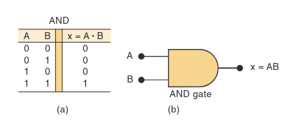
The next gate is the AND gate. An AND gate is much stricter. Its output will be HIGH (1) only if all of its inputs are HIGH (1). If even one input is LOW (0), the output will be LOW (0).
Analogy: Making a Peanut Butter & Jelly Sandwich. To make a proper PB&J, you need peanut butter AND you need jelly.
- If you have neither (Peanut Butter=0, Jelly=0), you can’t make it (Output=0).
- If you only have peanut butter but no jelly (Peanut Butter=1, Jelly=0), you can’t make it (Output=0).
- If you only have jelly but no peanut butter (Peanut Butter=0, Jelly=1), you can’t make it (Output=0).
- Only if you have both peanut butter AND jelly (Peanut Butter=1, Jelly=1) can you make the sandwich (Output=1).
Here’s the truth table and symbol for a two-input AND gate:
3. The NOT Gate (Inverter): The “Opposite”
The last of our three basic components is the NOT gate, also called an inverter. This one is the simplest of all. It has only one input and one output. Its job is simply to take the input and produce the opposite logic level as the output.
- If the input is HIGH (1), the output is LOW (0).
- If the input is LOW (0), the output is HIGH (1).
- Analogy: A “Bizarro” Clone. Imagine you have a clone who does the exact opposite of everything you do. When you are awake (1), your clone is asleep (0). When you are asleep (0), your clone is awake (1).
Here’s the truth table and symbol for a NOT gate:
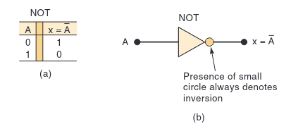
The small circle on the output of the symbol signifies inversion. You’ll see this circle used often in logic diagrams.
And that’s it! With just these three simple operations—OR, AND, and NOT—we can construct every possible digital circuit imaginable. They are the atoms of the digital universe. In the next post, we’ll see how to combine them to create more complex logic.
Contact Me
Let's connect with me
2025 Muhamad Rizki Kadafi. All Rights Reserved.