From Symbols to Logic: Speaking the Language of Circuits
In our last post, we met the three fundamental building blocks of the digital world: the AND, OR, and NOT gates. These simple components are the key to all digital decision-making. But rarely do they work alone. They are almost always combined to form more complex and useful circuits.
So, how do we talk about these combinations? Drawing diagrams for every circuit is possible, but it can get complicated fast. We need a more concise way to describe exactly what a logic circuit does. This is where Boolean algebra, the language of logic, comes in.
Describing a Logic Circuit with Algebra
Think of a logic circuit diagram as a sentence. Boolean algebra is the tool we use to write that sentence down. Any logic circuit, no matter how complex, can be described with a single Boolean expression.
The symbols are straightforward:
- AND is represented by a dot (
.), just like multiplication. So,A AND Bis writtenA . Bor often justAB. - OR is represented by a plus sign (
+). So,A OR Bis writtenA + B. - NOT is represented by a bar over the variable. So,
NOT Ais written asĀ.
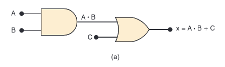
To find its expression, we work from the inputs to the output:
- The inputs
AandBgo into an AND gate. The output of that gate isAB. - That result (
AB) then goes into an OR gate along with inputC. - The final output,
x, is thereforex = AB + C.
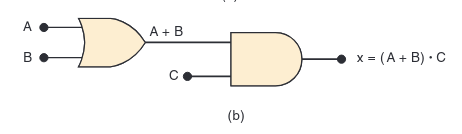
A Note on Parentheses and Precedence: What if the OR gate comes before the AND gate?.
Just like in regular math, we use parentheses. The rule is: AND operations are performed before OR operations,
unless parentheses tell you otherwise. The expression for the circuit below would be x = (A + B)C.
Without the parentheses, it would mean A + BC, which is a completely different circuit!
Evaluating a Circuit’s Output
Once you have the Boolean expression, you have the power to predict the circuit’s output for any set of inputs without ever building it! This is called evaluating the expression.
Let’s use our first expression, x = AB + C. What will the output x be if A=1, B=1, and C=0?
- Substitute the values:
x = (1 . 1) + 0 - Perform the AND operation first:
1 . 1 = 1 - Perform the OR operation:
x = 1 + 0 - Find the result:
x = 1So, for that specific input combination, the output will be HIGH (1). It’s that simple! This process allows engineers to analyze and test circuits just by using algebra.
Drawing a Circuit from a Boolean Expression
This is the reverse process, where we start with an expression and create the circuit diagram. It’s like having a recipe and buying the ingredients.
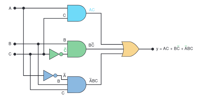
Let’s use the expression: y = AC + B̄C + ĀBC
- Identify the final operation. The final operation here is the OR (
+) that combines three terms. This means the last gate in our circuit will be a three-input OR gate. - Identify the inputs to the final gate. The inputs to this OR gate are the three terms:
AC,B̄C, andĀBC. - Create the logic for each input term. Each of these terms is an AND product.
This means we’ll need three separate AND gates to create them:
- An AND gate with inputs
AandCto produceAC. - An AND gate with inputs
B̄andCto produceB̄C. - An AND gate with inputs
Ā,B, andCto produceĀBC. - We will also need inverters (NOT gates) to create
ĀandB̄from the originalAandBinputs.
- An AND gate with inputs
- Combine it all. Now, we just connect the outputs of our three AND gates to the inputs of our one OR gate.
By learning to describe, evaluate, and implement circuits with Boolean algebra, we gain a powerful set of tools to analyze and design any digital system.
Contact Me
Let's connect with me
2025 Muhamad Rizki Kadafi. All Rights Reserved.